Topology
Topology is a type of association in LIDS. There are two types of topology associations: Linear topology association – for linear graph and Areal topology association – for areal graph.
Linear Topology
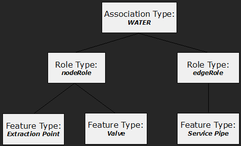
Linear topology association is a binary association with nodeRole and edgeRole roles. All feature types that can act as nodes in the linear graph are included in the nodeRole. Similarly, all feature types that can act as edges in the linear graph are included in the edgeRole.
Linear topology graph can be directed or undirected. There is no edge direction in the undirected linear topology graph as it is unimportant. On the other hand, the directed linear graph has all edges directed. Every edge in the directed graph has start node and end node.
Graph creation
Graph elements – nodes and edges are derived from standard features’ geometry. The graph elements are created / updated / deleted when source features are created, updated / deleted. Connection between edges and nodes is derived according to spatial position. If a node is created at the start / end of an edge, they are topologically connected.
Point features
Features with point geometry can be used to create nodes. Usually, one node feature is represented by a single node in the topology graph.
Following limitations exist:
-
Two nodes of the same graph can’t exist on the same position. It’s not possible to construct two point features defined as nodes of the same graph on the same coordinates.
-
Multigeometry is prohibited for point features defined as nodes
Linear features
Features with linear geometry can be used to create edges but also nodes. One linear feature can be represented by one or many topology edges. If there are usually nodes situated on the inner vertexes of lines, it is useful to split the line feature into several edges. Then the inner vertexes have correct topology connection to the topology edges. The definition for splitting edge features into many topology edges is included in the edge role metadata definition.
One feature in a node role can be represented by more than one topology node also. This unusual situation can only happen when node have a line-string geometry. For feature vertexes topology nodes are created and the nodes are connected by system edges.
System nodes
System node is special kind of node not related to point feature. It can’t be created manually by the user. System node is generated automatically on edge end, if there is nonstandard node in the specified distance. Typically, system nodes are generated after constructing linear features away from point features.
When point feature is created on the position where system node exists, the system node is replaced by the standard one.
Example: The example of simple linear graph definition for Water category.
Undirected graph
There are no directed edges in the undirected linear topology graph. The direction for the graph is not important.
Example: Definition of simple linear graph Water.
<ber:linearTopologyAssoc xmlns:ber="http://www.berit.com/ber"
     id="ast_01" name="WATER" dbName="WATER"
     snapRadius="0.5" update="online">
  <!-- Defines the Node Role -->
  <ber:nodeRole id="ast_01_node" name="Node of Water graph">
    <ber:description>Node of Water graph</ber:description>
    <ber:nodeType systemEdge="none">
      <!-- Extraction Point -->
      <ber:featureType refId="ft_5010200"/>
    </ber:nodeType>
    <ber:nodeType systemEdge="none">
      <!-- Valve -->
      <ber:featureType refId="ft_5011100"/>
    </ber:nodeType>
    <ber:pointSymbolizer>
      <se:Graphic>
        <se:ExternalGraphic>
          <se:OnlineResource xlink:href="resource.xml#ber_LIDSdemo/35"/>
          <se:Format/>
        </se:ExternalGraphic>
      </se:Graphic>
      <ber:rgbColor>#FF0000</ber:rgbColor>
    </ber:pointSymbolizer>
  </ber:nodeRole>
  <!-- Defines the Edge Role -->
  <ber:edgeRole id="ast_01_edge" name="Edge of Water graph">
    <ber:edgeType systemNode="terminal" processVertices="terminal">
      <!-- Service Pipe -->
      <ber:featureType refId="ft_5012200"/>
    </ber:edgeType>
    <ber:lineSymbolizer>
      <se:Stroke>
        <se:SvgParameter name="stroke">#FF0000</se:SvgParameter>
        <se:SvgParameter name="stroke-width">3</se:SvgParameter>
      </se:Stroke>
    </ber:lineSymbolizer>
  </ber:edgeRole>
</ber:linearTopologyAssoc>
Linear Topology Association
A linear topology association is defined by the linearTopologyAssoc XML element. There are following important attributes in the definition:
Attributes
-
id – Unique identifier of the linear topology association.
-
name – Name of the linear topology association.
-
dbName – The database table prefix for topology tables. Following tables are created xxx_NODE, xxx_EDGE, where xxx is the value of dbName attribute.
-
snapRadius – The double tolerance value. It is the maximal value for considering two nodes to be identical.
-
update – The update flag. One of online, batch. The online graph is updated online, when master features are updated (inserted, updated, deleted). The batch flag defines the linear graph to be updated only in a batch mode. The online flag allows batch updating also.
Node Role
The node role contains one or more node types defined by a nodeType XML element. The nodeRole is defined inline – it means that the actual definition of nodeRole is inside the linearTopologyAssoc XML element
Attributes
-
id – Unique identifier of the node role.
-
name – Name of the node role.
Node Type
The nodeType XML element aggregates feature types that should be considered to be nodes in the graph. There can be one or more feature type references included in the node type definition.
Attributes
- systemEdge – (none, all). This parameter makes sense only for linear feature types. When set to all, features with line-string geometry can be used as topology nodes. For each vertex of the feature a node is created. Nodes are then connected by system edges. When none is defined, features with line-string geometry cannot be used in the topology as nodes.
Inner elements
- featureType – List of feature type references. All referenced feature types can be topology nodes in the graph. Cannot be empty.
Point Symbolizer
Defines symbology for graph nodes visualization.
Edge Role
The edgeRole XML element contains one or more edge types. The edgeRole is defined inline – it means that the actual definition of edgeRole is inside the linearTopologyAssoc.
Attributes
-
id – Unique identifier of the edge role.
-
name – Name of the edge role.
Edge Type
The edgeType XML element aggregates feature types that should be edges in the linear graph. There can be one or more feature type references included in the edge type. The edge type contains two attributes systemNode and processVertices.
Attributes
-
systemNode – (all, inner, terminal) It defines the possibility to create system nodes when needed. Whenallis selected there are no restrictions where to create system nodes. Wheninneris selected the system nodes can be created only on internal vertexes of a line-string feature. This means: the terminal nodes must be standard nodes – point features must exist at the start and end of the line string. Whenterminalis selected the system nodes can be created only on terminal vertexes of a line-string feature. This means: point features must exist at the internal vertexes of the line string.
-
processVertices – (all, terminal) It defines the behavior of the algorithm for creating edges from features. WhenprocessVerticesis set toallit means that a line-string feature should be divided into several lines. There is an edge created from each line. When set toterminalfor a one line-string feature there will be only one edge created.
Inner elements
- featureType – List of feature type references. All referenced feature types can be topology edges in the graph. Cannot be empty.
Line Symbolizer
Defines symbology for graph edges visualization.
Directed graph
The directed linear topology graph is a graph where each edge is directed. There is always a start node and end node for each edge in the graph. AS the direction of edges is defined by the direction of geometries, the definition of a directed and undirected topology graph is almost same.
Example: Definition of simple linear directed graph Water.
<ber:linearDirectedTopologyAssoc xmlns:ber="http://www.berit.com/ber"
     id="ast_01" name="WATER" dbName="WATER"
     snapRadius="0.5" update="online">
  <!-- Defines the Node Role -->
  <ber:nodeRole id="ast_01_node" name="Node of Water graph">
    <ber:description>Node of Water graph</ber:description>
    <ber:nodeType systemEdge="none">
      <!-- Extraction Point -->
      <ber:featureType refId="ft_5010200"/>
    </ber:nodeType>
    <ber:nodeType systemEdge="none">
      <!-- Valve -->
      <ber:featureType refId="ft_5011100"/>
    </ber:nodeType>
  </ber:nodeRole>
  <!-- Defines the Edge Role -->
  <ber:edgeRole id="ast_01_edge" name="Edge of Water graph">
    <ber:edgeType systemNode="terminal" processVertices="terminal">
      <!-- Service Pipe -->
      <ber:featureType refId="ft_5012200"/>
    </ber:edgeType>
  </ber:edgeRole>
</ber:linearDirectedTopologyAssoc>
Constraints
There is a possibility to define constraints defining which types of nodes can be connected to which types of edges. The constraints are based on feature type x feature type restrictions. There are node constraints and edge constraints. Their meaning differs depending on the type of graph – directed or undirected.
Undirected constraints
-
Node Constraint – Defines possible feature types in the edge role which a feature type in the node role can be connected to.
-
Edge Constraint – Defines pair of feature types in the node role which a feature type in the edge role can be connected by.
Directed constraints
-
Node Constraint – For a feature type in the node role defines a set of feature types in the edge role that can go out from the node and a set of feature types in the edge role that can come into the node. There is a possibility to define more constraints – combination of incoming and outgoing edges.
-
Edge Constraint – For a feature type in the edge role it defines a set of feature types in the node role which can start in and a set of feature types in the edge role which can end to. There can be more constraints – combinations of start and end nodes.
Node constraints are defined inside thenodeTypeelement. Edge constraints are defined inside theedgeTypeelement.
Constraints for undirected graph
Node Constraints
Node constraints for undirected graph are defined in node types.
Example: Definition of node constraints.
<ber:nodeRole id="ast_01_node" name="Node of Water graph">
  <ber:nodeType systemEdge="none">
    <ber:featureType refId="ft_5010200"/>  <!-- Extraction Point -->
    <ber:constraint>
      <ber:featureType refId="ft_5012200"/> <!-- Service Pipe -->
    </ber:constraint>
  </ber:nodeType>
  <ber:nodeType systemEdge="none">
    <ber:featureType refId="ft_5011100"/> <!-- Valve -->
    <ber:constraint>
      <ber:featureType refId="ft_5012200"/>  <!-- Service Pipe -->
    </ber:constraint>
  </ber:nodeType>
</ber:nodeRole>
Constraint
The constraint element for nodes in undirected linear graph contains list of feature type references that are included in the edge role. For the specified list of feature types in the actual node type it defines the possible feature types in the edge role the node can be connected to. If the list is empty, then this node cannot be connected to any edge. When the constraint element is not present, node can be connected to all features.
Inner elements
- featureType – List of feature type references. All referenced feature types can be connected to the node. If there is no feature type reference, then this node cannot be connected to any edge.
Edge Constraints
Edge constraints for undirected graph are defined in edge types.**Example:**Definition of edge constraints.
<ber:edgeRole id="ast_01_edge" name="Edge of Water graph">
  <ber:edgeType systemNode="terminal" processVertices="terminal">
    <ber:featureType refId="ft_5012200"/> <!-- Service Pipe -->
    <ber:constraint allowsSystemNode="true">
      <ber:featureType refId="ft_5010200"/> <!-- Extraction Point -->
      <ber:featureType refId="ft_5011100"/> <!-- Valve -->
    </ber:constraint>
  </ber:edgeType>
</ber:edgeRole>
Constraint
The constraint element for edges in undirected linear graph contains list of feature type references that are included in the node role. For the specified list of feature types in the actual edge type it defines the possible feature types in the node role the edge can be connected to. If the list is empty, then this edge cannot be connected to any feature node. When the constraint element is not present, the edge can be connected to all feature nodes.
Attributes
- allowsSystemNode – (true, false) This flag defines whether the edge can be connected to a system node – a node generated by the system; such node does not refer to a feature.
Inner elements
- featureType – List of feature type references. All referenced feature types can be connected to the node. When no feature type is referenced then this edge cannot be connected to any feature node.
Constraints for directed graph
Constraints for directed graph allows defining incoming and outgoing edges for nodes and start or end nodes for edges.
We will define directed graph with directed constraint in the following example. Consider following situation. Let's have two node types – Extraction Point and Valve and one node type – Service Pipe. We will define directed graph. Consider following restrictions:
-
Service pipe can start only in Valve
-
Service pipe can end in Extraction Point, Valve or system node.

Node Constraints
Node constraints are defined in node types. For the specified list of feature types in the actual node type it defines the possible set of incoming edge feature types and possible set of outgoing edge feature types.
Example: Definition of directed node constraints.
<ber:nodeRole id="ast_01_node" name="Node of Water graph">
  <!-- systemEdge="none" -> only point geometries are allowed -->
  <ber:nodeType systemEdge="none">
    <ber:featureType refId="ft_5010200"/> <!-- Extraction Point -->
    <ber:directedConstraintArray>
      <!-- Only Service Pipe feature can be incoming for this node type -->
      <ber:directedConstraint>
        <ber:inEdge>
          <ber:featureType refId="ft_5012200"/> <!-- Service Pipe -->
        </ber:inEdge>
      </ber:directedConstraint>
    </ber:directedConstraintArray>
  </ber:nodeType>
  <ber:nodeType systemEdge="none">
    <ber:featureType refId="ft_5011100"/> <!-- Valve -->
    <ber:directedConstraintArray>
      <!-- Only Service Pipe feature can be outgoing for this node type -->
      <ber:directedConstraint>
        <ber:outEdge>
          <ber:featureType refId="ft_5012200"/> <!-- Service Pipe -->
        </ber:outEdge>
      </ber:directedConstraint>
    </ber:directedConstraintArray>
  </ber:nodeType>
</ber:nodeRole>
-
directedConstraintArray – holds list of directedConstraint elements.
-
directedConstraint – sequence of inEdge and outEdge elements. If the inEdge or outEdge element is missing it means that all incoming feature edges or all outgoing feature edges are allowed.
-
inEdge – contains list of feature types in the edge role that can come into the node. If the list is empty, it means that no feature edges can be incoming to the node.
-
outEdge – contains list of feature types in the edge role that can go out from the node. If the list is empty, it means that no feature edges can be outgoing from the node.
Edge Constraints
Edge constraints for directed graph defines possible start nodes and end nodes for an edge type. Edge constraints are defined inside the edgeType definition.
Example: Definition of edge constraint
<ber:edgeRole id="ast_01_edge" name="Edge of Water graph">
  <ber:edgeType systemNode="terminal" processVertices="terminal">
    <ber:featureType refId="ft_5012200"/> <!-- Service Pipe -->
    <ber:directedConstraintArray>
      <ber:directedConstraint>
        <!-- start nodes constraint
             -> Service Pipe can start only in Valve feature -->
        <ber:startNode allowsSystemNode="false">
           <!-- allowsSystemNode="false" -> the edge cannot
                start in a system node -->
          <ber:featureType refId="ft_5011100"/>  <!-- Valve -->
        </ber:startNode>
        <!-- end nodes constraint
             -> Service Pipe can end in Valve, Extraction Point
                or system node -->
        <ber:endNode allowsSystemNode="true">
           <!-- allowsSystemNode="true" -> the edge can
                start in a system node -->
          <ber:featureType refId="ft_5011100"/>  <!-- Valve -->
          <ber:featureType refId="ft_5010200"/> <!-- Extraction Point -->
        </ber:endNode>
      </ber:directedConstraint>
    </ber:directedConstraintArray>
  </ber:edgeType>
</ber:edgeRole>
-
directedConstraintArray – Holds list of directedConstraint elements.
-
directedConstraint – Sequence of startNode and endNode elements. If the inEdge or outEdge element is missing it means that all incoming feature edges or all outgoing feature edges are allowed. If the startNode element is missing, it means that the edge can start in all feature types in node role including system nodes. If the endNode element is missing, it means that the edge can end in all feature types in node role including system nodes.
-
startNode – Defines a list of start feature types in the node role. If no feature type is defined it means that the edge can start in no node feature. The startNode element contains one attribute allowsSystemNode (true, false). This flag defines whether the edge can start in a system node – a node generated by the system; node does not refer to a feature.
-
endNode – Defines a list of end feature types in the node role for the edge. If no feature type is defined it means that the edge can end in no node feature. The endNode element contains one attribute allowsSystemNode (true, false). This flag defines whether the edge can start in a system node – a node generated by the system; node does not refer to a feature.
Example: We will define a directed graph with two feature nodes – Valve and Extraction Point and one feature edge – Service Pipe with following restrictions:
-
Service Pipe can start in a Valve and end in a Valve
-
Service Pipe can start in a Valve and end in a system node
-
Service Pipe can start in a system node and end in Extraction point

The xml definition for the constraint looks like following:
<ber:linearDirectedTopologyAssoc
     id="ast_01" name="WATER" dbName="WATER" snapRadius="0.5"
     update="online">
  <ber:nodeRole id="ast_01_node" name="Node of Water graph">
    <ber:nodeType systemEdge="none">
      <ber:featureType refId="ft_5010200"/> <!-- Extraction Point -->
      <ber:directedConstraintArray>
        <ber:directedConstraint>
          <ber:inEdge>
            <!-- Only Service Pipe can come in the node -->
            <ber:featureType refId="ft_5012200"/> <!-- Service Pipe -->
          </ber:inEdge>
          <ber:outEdge>
            <!-- No edges can go out -->
          </ber:outEdge>
        </ber:directedConstraint>
      </ber:directedConstraintArray>
    </ber:nodeType>
    <ber:nodeType systemEdge="none">
      <ber:featureType refId="ft_5011100"/> <!-- Valve -->
      <ber:directedConstraintArray>
        <ber:directedConstraint>
          <ber:inEdge>
            <!-- Only Service Pipe can come in the node -->
            <ber:featureType refId="ft_5012200"/> <!-- Service Pipe -->
          </ber:inEdge>
          <ber:outEdge>
            <!-- Only Service Pipe can go out from the node -->
            <ber:featureType refId="ft_5012200"/>  <!-- Service Pipe -->
          </ber:outEdge>
        </ber:directedConstraint>
      </ber:directedConstraintArray>
    </ber:nodeType>
  </ber:nodeRole>
  <ber:edgeRole id="ast_01_edge" name="Edge of Water graph">
    <ber:edgeType systemNode="terminal" processVertices="terminal">
      <ber:featureType refId="ft_5012200"/> <!-- Service Pipe -->
      <ber:directedConstraintArray>
        <ber:directedConstraint>
          <ber:startNode allowsSystemNode="false">
            <!-- Service Pipe can start in Valve -->
            <ber:featureType refId="ft_5011100"/> <!-- Valve -->
          </ber:startNode>
          <ber:endNode allowsSystemNode="true">
            <!-- Service Pipe can end in Valve or system node -->
            <ber:featureType refId="ft_5011100"/> <!-- Valve -->
          </ber:endNode>
        </ber:directedConstraint>
        <ber:directedConstraint>
          <ber:startNode allowsSystemNode="true">
            <!-- Service Pipe can start in a system node -->
          </ber:startNode>
          <ber:endNode allowsSystemNode="false">
            <!-- Service Pipe can end in a Extraction point -->
            <ber:featureType refId="ft_5010200"/> <!-- Extraction point -->
          </ber:endNode>
        </ber:directedConstraint>
      </ber:directedConstraintArray>
    </ber:edgeType>
  </ber:edgeRole>
</ber:linearDirectedTopologyAssoc>
Bridges
Bridges are nongraphical, topological only elements used for connecting standard elements of linear graph. Bridges are considered during tracing functionality and enable tracing to pass through elements which are not geometrically connected. Bridges can connect either two nodes or two edges of the same or different graphs. Apart from nodes and edges, bridges are not derived from the source features automatically and must be created manually by the user.
Special kind of bridges connect nodes or edges created by features with shared semantics. Such bridges can be generated automatically.
Metadata definition of a bridge – linearTopologyConnection - includes (apart from the standard id and name attributes):
-
type – bridge type can be edgeToEdge or nodeToNode
-
startRole and endRole ftItem – feature type connected by the starting or ending node of the bridge
-
lineSymbolizer – symbology used to display bridge in the client application
Example: Definition of edge-to-edge bridge
<ber:linearTopologyConnection id="ltc_1" name="Pipeline segments brige" type="edgeToEdge">
  <ber:startRole id="start_r_asltc_1" name="Start pipeline segment role">
    <ber:ftItem refId="ft_5012100"/>
  </ber:startRole>
  <ber:endRole id="end_r_asltc_1" name="End pipeline segment role">
    <ber:ftItem refId="ft_5012100"/>
  </ber:endRole>
  <ber:lineSymbolizer>
    <se:Stroke>
      <se:SvgParameter name="stroke">#880000</se:SvgParameter>
      <se:SvgParameter name="stroke-width">1</se:SvgParameter>
    </se:Stroke>
  </ber:lineSymbolizer>
</ber:linearTopologyConnection>
Example: Definition of node-to-node bridge
<ber:linearTopologyConnection id="ltc_2" name="Station - Valve bridge" type="nodeToNode">
  <ber:startRole id="start_r_asltc_2" name="Station role">
    <ber:ftItem refId="ft_5010100"/>
  </ber:startRole>
  <ber:endRole id="end_r_asltc_2" name="Valve role">
    <ber:ftItem refId="ft_5011100"/>
  </ber:endRole>
  <ber:lineSymbolizer>
    <se:Stroke>
      <se:SvgParameter name="stroke">#990000</se:SvgParameter>
      <se:SvgParameter name="stroke-width">4</se:SvgParameter>
    </se:Stroke>
  </ber:lineSymbolizer>
</ber:linearTopologyConnection>