Feature Symbology
The definition of feature symbology is strictly separated from its geometry. It results in the very flexible system where features are symbolized just before their presentation. The symbology definition is feature type based. It can be either static (the same for all instances of the feature type in any scale) or dynamic (varies according to the current scale and/or feature attribute values). Every feature type can define one default static and one default dynamic symbology. While the static symbology is the part of the feature type definition, the dynamic symbology refers special LIDS metadata section (in thematization.xml).
It is not necessary to define symbology in its full form. It is possible to define any subset of symbology properties (partial symbolizers) and the system itself fills the missing properties from some super symbology definition in any part of metadata. The super symbology varies for various symbology definitions.
Static Symbology
The LIDS symbology definition is based on OGC Symbology Encoding (SE) specification. It means the LIDS symbology definition is very easily shareable among other systems and tools supporting the SE standard. Each LIDS geometry type has its own type of symbology definition. There are four basic symbology types in LIDS: point, curve, surface, text.
Curve symbology
Example: Curve symbology definition.
<ber:featureType id="ft_5012100" name="Main pipeline segment"
                 parentId="ft_5012000" abstract="false">
  <ber:description>Main pipeline segment</ber:description>
  <ber:masterGraphics nillable="true">
    <ber:curveGraphicType>
      <ber:symbology>
        <ber:lineSymbolizer>
          <se:Stroke>
            <se:GraphicStroke>
              <se:Graphic>
                <se:ExternalGraphic>
                  <se:OnlineResource xlink:href="resource.xml#ls_4"/>
                  <se:Format/>
                </se:ExternalGraphic>
              </se:Graphic>
            </se:GraphicStroke>
            <se:SvgParameter name="stroke">#1C32FF</se:SvgParameter>
            <se:SvgParameter name="stroke-opacity">1</se:SvgParameter>
            <se:SvgParameter name="stroke-width">2</se:SvgParameter>
          </se:Stroke>
        </ber:lineSymbolizer>
      </ber:symbology>
    </ber:curveGraphicType>
  </ber:masterGraphics>
  ...
</ber:featureType>
-
symbology – Encapsulates complete static symbology definition.
-
lineSymbolizer – SE based symbology definition for curve geometries. Only the above set of subelements is supported in LIDS.
-
GraphicStroke – The only one of the SE linestroke types that is supported by LIDS. It references the linestyle for stroke rendering defined as LIDS resource.
-
The Stroke definition contains the following set of SVG Parameters:
-
stroke – Specifies the solid color that will be used for a stroke. The color value is RGB-encoded using two hexadecimal digits per primary-color component, in the order Red, Green, Blue, prefixed with a hash (#) sign.
-
stroke-opacity – Specifies the level of translucency to use when rendering the stroke. The value is encoded as a float between 0.0 and 1.0 with 0.0 representing completely transparent and 1.0 representing completely opaque.
-
stroke-width – Specifies the absolute width (thickness) of a stroke in pixels encoded as a float. Maximum value 31.
-
Line width
Line width is defined in LIDS as unitless index values between 0 and 31. However, in some situations it’s necessary to convert these width indexes to different units.
The line width used for displaying can be different than the one used for printing. It’s possible to map a display width to the printing width (specified in device independent points DIP - 1/96 inch). The mapping is common for whole project and is defined in lineWeights element in presentation.xml.
Example: Line weights for printing mapping.
  <ber:plotting>
    <!-- Default symbolizer for north arrow in map output -->
    <ber:defaultNortharrow>
      <ber:pointSymbolizer>
        <se:Graphic>
          <se:ExternalGraphic>
            <se:OnlineResource xlink:href="resource.xml#fontname/66"/>
            <se:Format/>
          </se:ExternalGraphic>
        </se:Graphic>
        <ber:rgbColor>#C80000</ber:rgbColor>
        <ber:symbolHeight>36</ber:symbolHeight>
      </ber:pointSymbolizer>
    </ber:defaultNortharrow>
    <!-- Line weights mapping -->
    <ber:lineWeights>
      <ber:lineWeight display="0" print="0.025"/>
      <ber:lineWeight display="1" print="0.125"/>
      <ber:lineWeight display="2" print="0.25"/>
      <ber:lineWeight display="3" print="0.35"/>
      <ber:lineWeight display="4" print="0.5"/>
      <ber:lineWeight display="5" print="0.75"/>
      <ber:lineWeight display="6" print="1"/>
    </ber:lineWeights>
  </ber:plotting>
DWG file format defines line weights in mm. It’s possible to map line weight indexes used in LIDS to the DWG line weights in mm. This mapping is considered when exporting / importing DWG and when displaying DWG. The mapping is common for whole project and is defined in dwgLineWeights element in presentation.xml.
Example: Line weights for DWG mapping.
  <ber:dwgLineWeights>
    <ber:dwgLineWeight display="0" dwg="0"/>
    <ber:dwgLineWeight display="1" dwg="0.13"/>
    <ber:dwgLineWeight display="2" dwg="0.30"/>
    <ber:dwgLineWeight display="3" dwg="0.40"/>
    <ber:dwgLineWeight display="4" dwg="0.53"/>
    <ber:dwgLineWeight display="5" dwg="0.70"/>
    <ber:dwgLineWeight display="6" dwg="0.80"/>
  </ber:dwgLineWeights>
User line style
To display line features, it is possible to use user line styles. These are specified by a data model. Each style must be stated in resource.xml together with list of available formats and name of files containing the style definition. Style definition files are stored as project resource files on application server and are cached by LIDS client when logging in to the project
From technological reasons, individual line styles definitions for different clients use different formats:
- LIDS Explorer and Browser line styles are defined in XML (e.g. ls_linestyle3.xml) and are stored in {project_folder}\lids-as\resources\linestyle\xml
- LIDS Edit line styles are defined in RSC or LIN (e.g.ls_linestyle3.rsc, ls_linestyle.lin) and are stored in {project_folder}\lids-as\resources\linestyle\rsc or {project_folder}\lids-as\resources\linestyle\lin
- LIDS Mobile line styles are defined in JSON
Definition in XML format must be prepared for purposes of map outputs also for LIDS Edit.
Starting with version 7.1.6, the solid line is a built-in system line style (system.linestyle#solid) and needs no XML definition (formerly ls_0).
Individual line styles definitions have to be registered in resource.xml. Here the different formats are bound under the common line style identifiers, which are subsequently referenced in, thematization.xml and model.xml as common definitions.
Example: Reference to the style in resource.xml.
  <ber:lineStyleArray>
...
    <ber:lineStyle id="ls_3" name="3">
      <ber:formatArray>
        <!-- Styles 1 – 7 don’t specify file attribute for RSC format -->
        <ber:format extResId="3" name="rsc"/>
        <ber:format extResId="3" name="lin"/>
        <ber:format file="ls_default.xml" name="xml"/>
        <ber:format file="ls_default.json" name="json"/>
      </ber:formatArray>
    </ber:lineStyle>
...
    <ber:lineStyle id="KAN_POD_SPL" name="Waste water 7">
      <ber:formatArray>
        <ber:format extResId="KAN_POD_SPL" file="ls_linestyle3.xml" name="xml"/>
        <ber:format extResId="KAN_POD_SPL" file="ls_linestyle3.rsc" name="rsc"/>
        <ber:format extResId="KAN_18" file="ls_kan.json" name="json"/>
      </ber:formatArray>
    </ber:lineStyle>
...
    <ber:lineStyle id="STYLE_COMPLEX_3" name="Style complex 3">
      <ber:formatArray>
        <ber:format extResId="STYLE_C3" file="ls_linestyle3.xml" name="xml"/>
        <ber:format extResId="STYLE_COMPLEX_3" file="ls_linestyle3.json" name="json"/>
      </ber:formatArray>
    </ber:lineStyle>
...
  </ber:lineStyleArray>
Example: Reference to the style in thematization.xml.
    <ber:featureTypeStyle id="fs_route" name="Route">
      <se:FeatureTypeName>ft_e_route</se:FeatureTypeName>
      <ber:combinedRule defaultScale="true" id="route_0" name="Route">
        <ber:lineSymbolizer>
          <se:Stroke>
            <se:GraphicStroke>
              <se:Graphic>
                <se:ExternalGraphic>
                  <ber:onlineResource>
                    <ber:recode fallbackValue="system.linestyle#solid">
                      <se:LookupValue>
                        <ogc:PropertyName>at_5120006_s</ogc:PropertyName>
                      </se:LookupValue>
                      <ber:mapItem>
                        <ber:data>1</ber:data>
                        <ber:value id="r_ls_solid" name="Operation status: In operation">system.linestyle#solid</ber:value>
                      </ber:mapItem>
                      <ber:mapItem>
                        <ber:data>0</ber:data>
                        <ber:value id="r_ls_3" name="Operation status: Out of service">resource.xml#ls_3</ber:value>
                      </ber:mapItem>
                      <ber:elseMapItem>
                        <ber:value id="r_ls_else">system.linestyle#solid</ber:value>
                      </ber:elseMapItem>
...
    </ber:featureTypeStyle>
Example: Reference to the style in model.xml.
    <ber:featureType id="ft_5060000" name="Service OU - polygon" parentId="ft_5060000_s" abstract="false" sharedSemantics="true">
      <ber:description>Area</ber:description>
      <ber:masterGraphics nillable="false">
        <ber:surfaceGraphicType>
          <ber:symbology>
            <ber:polygonSymbolizer>
              <ber:fill>
                <se:SvgParameter name="fill">#808080</se:SvgParameter>
                <se:SvgParameter name="fill-opacity">0.5</se:SvgParameter>
                <ber:fillStyle>solid</ber:fillStyle>
              </ber:fill>
              <se:Stroke>
                <se:GraphicStroke>
                  <se:Graphic>
                    <se:ExternalGraphic>
                      <se:OnlineResource xlink:href="resource.xml#ls_3"/>
                      <se:Format/>
                    </se:ExternalGraphic>
...
      </ber:masterGraphics>
RSC linestyle definitions for DGN export and for LIDS Edit display
For DGN export, it's strongly recommended to import the line style definitions directly into the project seed.dgn. This seed.dgn is used by both LIDS Edit and LIDS Explorer. In this setup, the line style definition in resource.xml contains format name="rsc", but does not include the file attribute. This configuration instructs the system to search for the line style definition directly in seed.dgn.
LIDS Edit generates DGN file(s) whenever LIDS data needs to be displayed. These DGN files are then rendered by MicroStation. Therefore, the mechanism for handling line styles is essentially the same when
- displaying data in LIDS Edit, and
- when exporting data to a DGN file.
It's still possible to read the line styles from an external RSC file, but this approach has certain limitations.
Case 1: The file attribute is specified in resource.xml
When the file attribute is defined:
- The RSC file is loaded from the specified external resource location for use in LIDS Edit
- The exported DGN file contains a reference to the external RSC resource file
- The external RSC file must be properly registered and accessible to MicroStation in order to correctly display the exported DGN file outside of LIDS Edit.
Example: Reference to the style in resource.xml - Case 1.
    <ber:lineStyle id="KAN_POD_SPL" name="Waste water 7">
      <ber:formatArray>
        <ber:format extResId="KAN_POD_SPL" file="ls_linestyle3.xml" name="xml"/>
        <ber:format extResId="KAN_POD_SPL" file="ls_linestyle3.rsc" name="rsc"/>
      </ber:formatArray>
    </ber:lineStyle>
Case 2: The file attribute is not specified in resource.xml
When the file attribute is not defined:
- LIDS Edit assumes that the RSC file has been imported into the seed.dgn file
- The exported DGN file contains an internal reference to the RSC data
- Displaying the exported DGN file in MicroStation outside of LIDS Edit relies solely on the internally stored RSC data and does not require a separate external RSC file.
Example: Reference to the style in resource.xml - Case 2.
    <ber:lineStyle id="STYLE_COMPLEX_3" name="Style complex 3">
      <ber:formatArray>
        <ber:format extResId="STYLE_C3" file="ls_linestyle3.xml" name="xml"/>
        <ber:format extResId="STYLE_COMPLEX_3" name="rsc"/>
      </ber:formatArray>
    </ber:lineStyle>
Line styles 1-7 are also referenced without including the file attribute. However, unlike custom line styles, they do not need to be imported into seed dgn.
Example: Reference to the style in resource.xml - Line styles 1-7.
    <ber:lineStyle id="ls_3" name="3">
      <ber:formatArray>
        <ber:format extResId="3" name="rsc"/>
        <ber:format extResId="3" name="lin"/>
        <ber:format file="ls_default.xml" name="xml"/>
        <ber:format file="ls_default.json" name="json"/>
      </ber:formatArray>
    </ber:lineStyle>
Linestyle definitions for LIDS Mobile
User line style logically consists of one line component and of an optional start and end symbol.
User line style consists of following parts:
-
One line component for which these properties can be singly set:
-
optionally symbol to be drawn at the beginning of curve
-
optionally symbol to be drawn at the end of curve
-
Line component definition consists of:
-
Used units (e.g. meters or pixels)
-
Optionally line component parts, so called dash-stroke, that defines size and relay of single parts. The parts can be of following types:
-
solid line
-
gap
-
symbol
-
text
-
-
Drawing mode
- continuous – the parts are drawn continuously along the whole curve
-
Optional parameter of minimal length – it can influence whether single parts of line components will be drawn - a dash-stroke is drawn if a total length of curve is grater or equal to specified minimal length
-
Way how to solve situation when there is not enough space for a dash-stroke part or when some of size conditions (mentioned above) is not fulfilled. Possible ways:
-
render solid line
-
render nothing (default behavior)
-
Start / end symbol properties:
-
definition of used symbol
-
used units (e.g. meters or pixels)
-
symbol size
-
symbol indent (distance in x and y direction from the beginning / end of curve towards the center of used symbol)
-
symbol rotation - it can be of two types:
-
relative – rotation by specified angle towards the given curve's segment
-
absolute – rotation towards global coordinate system
-
Dash-stroke part definition – symbol:
-
definition of used symbol
-
symbol size - units are taken over from the parent line component
-
symbol indent (distance in x and y direction from the dash-stroke part center towards the center of used symbol)
-
symbol rotation - it can be of two types:
-
relative – rotation by specified angle towards the given curve's segment
-
absolute – rotation towards global coordinate system
-
Dash-stroke part definition – text:
-
displayed text
-
used font
-
text height – it is taken over from the parent line component
-
text indent (distance in x and y direction from the dash-stroke part center towards the center of used text)
-
text rotation - it can be of two types:
-
relative – rotation by specified angle towards the given curve's segment
-
absolute – rotation towards global coordinate system
-
Symbols and texts are not clipped within a dash-stroke part (i.e. they can exceed dash-stroke part size).
Example: Definition of line styles and its components in JSON format – without symbols.
 [
   {
      "id" : "ls_1",
      "unit" : "pixel",
      "dashArray" : [
         {
            "type" : "DASH",
            "length" : 6
         },
         {
            "type" : "GAP",
            "length" : 4
         }
      ]
   },
   {
      "id" : "ls_2",
      "unit" : "pixel",
      "dashArray" : [
         {
            "type" : "DASH",
            "length" : 10
         },
         {
            "type" : "GAP",
            "length" : 7
         }
      ]
   },
   {
      "id" : "ls_3",
      "unit" : "pixel",
      "dashArray" : [
         {
            "type" : "DASH",
            "length" : 18
         },
         {
            "type" : "GAP",
            "length" : 13
         }
      ]
   },
   {
      "id" : "ls_4",
      "unit" : "pixel",
      "dashArray" : [
         {
            "type" : "DASH",
            "length" : 14
         },
         {
            "type" : "GAP",
            "length" : 5
         },
         {
            "type" : "DASH",
            "length" : 2
         },
         {
            "type" : "GAP",
            "length" : 5
         }
      ]
   },
   {
      "id" : "ls_5",
      "unit" : "pixel",
      "dashArray" : [
         {
            "type" : "DASH",
            "length" : 10
         },
         {
            "type" : "GAP",
            "length" : 10
         }
      ]
   },
   {
      "id" : "ls_6",
      "unit" : "pixel",
      "dashArray" : [
         {
            "type" : "DASH",
            "length" : 10
         },
         {
            "type" : "GAP",
            "length" : 5
         },
         {
            "type" : "DASH",
            "length" : 2
         },
         {
            "type" : "GAP",
            "length" : 5
         },
         {
            "type" : "DASH",
            "length" : 2
         },
         {
            "type" : "GAP",
            "length" : 5
         }
      ]
   },
   {
      "id" : "ls_7",
      "unit" : "pixel",
      "dashArray" : [
         {
            "type" : "DASH",
            "length" : 10
         },
         {
            "type" : "GAP",
            "length" : 5
         },
         {
            "type" : "DASH",
            "length" : 4
         },
         {
            "type" : "GAP",
            "length" : 5
         }
      ]
   }
]
Example: Definition of line styles and its components in JSON format – with symbols.
[
   {
      "id" : "example_1",
      "unit" : "metre",
      "dashArray" : [
         {
            "type" : "DASH",
            "length" : 0.5
         },
         {
            "type" : "GAP",
            "length" : 0.5
         }
      ]
   },
   {
      "id" : "example_3",
      "unit" : "pixel",
      "startSymbol" : {
         "font" : "arial.ttf",
         "symbol" : 42,
         "size" : 15,
         "rotation" : 45,
         "displacementX" : 1,
         "displacementY" : -1
      },
      "endSymbol" : {
         "font" : "arial.ttf",
         "symbol" : 42,
         "size" : 15,
         "rotation" : 45,
         "displacementX" : 1,
         "displacementY" : -1
      },
      "dashArray" : [
         {
            "type" : "DASH",
            "length" : 18
         },
         {
            "type" : "GAP",
            "length" : 13
         },
         {
            "type" : "TEXT",
            "length" : 13,
            "font" : "arial.ttf",
            "text" : "abc",
            "size" : 15,
            "rotation" : 45,
            "displacementX" : 1,
            "displacementY" : -1
         },
         {
            "type" : "SYMBOL",
            "length" : 2,
            "font" : "arial.ttf",
            "symbol" : 22,
            "size" : 15,
            "rotation" : 45,
            "displacementX" : 1,
            "displacementY" : -1
         }
      ]
   }
]
XML line style format
It’s necessary to specify basic information about line style in resource.xml as for other resources. Detailed definition of each style listed in resource.xml is prepared as a special XML file.
Example: Line style basic information in resource.xml.
    <ber:lineStyle id="ls_WASTE_WATER_PURE" name="Waste water pure">
      <ber:formatArray>
        <ber:format name="xml" file="ls_uap.xml"/>
      </ber:formatArray>
    </ber:lineStyle>
  ...
  </ber:lineStyleArray>
Example: Definition of line style and its components in XML format in ls_uap.xml file.
    <ber:component id="comp_waste_pure_c1" uom="http://www.opengeospatial.org/se/units/metre">
      <ber:stroke-dasharray>1[ber_LIDSdemo2_123] 1[ber_LIDSdemo2_123] -1 1[ber_LIDSdemo2_120]</ber:stroke-dasharray>
      <ber:segmentMode>center</ber:segmentMode>
      <ber:requiredLength>9</ber:requiredLength>
      <ber:outOfStrokeGlue>none</ber:outOfStrokeGlue>
      <ber:strokeArray>
        <ber:pointStroke id="ber_LIDSdemo2_123">
          <ber:pointSymbolizer>
            <se:Graphic>
              <se:ExternalGraphic>
                <!-- Symbol anchor point is always center-center -->
                <se:OnlineResource xlink:href="resource.xml#ber_LIDSdemo2/123"/>
                <se:Format/>
              </se:ExternalGraphic>
              <se:Size>2</se:Size>
              <se:Displacement>
                <se:DisplacementX>0</se:DisplacementX>
                <se:DisplacementY>0</se:DisplacementY>
              </se:Displacement>
            </se:Graphic>
            <ber:symbolHeight>2</ber:symbolHeight>
            <ber:rotation type="relative">0</ber:rotation>
          </ber:pointSymbolizer>
        </ber:pointStroke>
        <ber:pointStroke id="ber_LIDSdemo2_120">
...
        </ber:pointStroke>
      </ber:strokeArray>
    </ber:component>
...
    <ber:lineStyle id="ls_WASTE_WATER_PURE">
      <ber:components>
        <ber:component refId="comp_waste_pure_c1">
          <ber:perpendicularOffset>2</ber:perpendicularOffset>
        </ber:component>
        <ber:component refId="style_0">
          <ber:perpendicularOffset>-1</ber:perpendicularOffset>
        </ber:component>
      </ber:components>
    </ber:lineStyle>
...
  <ber:lineStyleArray>
User line style logically consists of one or more line components optionally shifted from a curve's axis and of an optional start and end symbol. Line components are defined separately in definition file with possibility to share them by more style definitions within one xml-file.
User line style consists of following parts:
- At least one line component (its definition reference) for which these properties can be singly set:
- perpendicular distance of shifting from a curve's axis - component will be drawn in this distance
- gap at the beginning of curve - component parts drawing will start after this gap
- gap at the end of curve - component parts drawing ends before this gap
- optionally symbol to be drawn at the beginning of curve
- optionally symbol to be drawn at the end of curve
Start / end symbol properties:
- definition of used symbol
- used units (e.g. meters or pixels)
- symbol size
- symbol indent (distance in x and y direction from the beginning / end of curve towards the center of used symbol)
- symbol rotation - it can be of two types:
- relative – rotation by specified angle towards the given curve's segment
- absolute – rotation towards global coordinate system
Line component definition consists of:
- Used units (e.g. meters or pixels)
- Optionally line component parts, so called dash-stroke, that defines size and relay of single parts. The parts can be of following types:
- solid line
- gap
- symbol
- text
- Drawing mode
- continuous – the parts are drawn continuously along the whole curve; in inner vertexes a dash-stroke is eventually “wrapped”
- by segments – the parts are drawn continuously along the single curve segments; in inner vertex a dash-stroke begins from its first part
- center in segment – for a single curve segment a dash-stroke is drawn just once and centered; segment length must be greater than a sum of lengths of dash-stroke parts
- Optional parameter of minimal length – in combination with drawing mode it can influence whether single parts of line components will be drawn
- continuous mode – a dash-stroke is drawn if a total length of curve is grater or equal to specified minimal length
- by segments mode – a dash-stroke is drawn for the segment if segment length is grater or equal to specified minimal length
- center in segment mode – a dash-stroke is drawn only if at once segment length is grater or equal to a sum of lengths of dash-stroke parts and is grater or equal to specified minimal length
- Way how to solve situation when there is not enough space for a dash-stroke part or when some of size conditions (mentioned above) is not fulfilled. Possible ways:
- render solid line
- render nothing (default behavior)
Dash-stroke part definition – symbol:
- definition of used symbol
- symbol size - units are taken over from the parent line component
- symbol indent (distance in x and y direction from the dash-stroke part center towards the center of used symbol)
- symbol rotation - it can be of two types:
- relative – rotation by specified angle towards the given curve's segment
- absolute – rotation towards global coordinate system
Dash-stroke part definition – text:
- displayed text
- used font
- text height – it is taken over from the parent line component
- text indent (distance in x and y direction from the dash-stroke part center towards the center of used text)
- text rotation - it can be of two types:
- relative – rotation by specified angle towards the given curve's segment
- absolute – rotation towards global coordinate system
Symbols and texts are not clipped within a dash-stroke part (i.e. they can exceed dash-stroke part size).
Line weight specified by a feature symbology is not applied to symbol / text parts of a dash-stroke.
Example: Line style with text component.

  <ber:lineStyleArray>
  ...
    <ber:lineStyle id="ls_PAM_REZERVACE_VPR">
      <ber:components>
        <ber:component refId="comp_pr_vpr">
          <ber:perpendicularOffset>0.0</ber:perpendicularOffset>
        </ber:component>
      </ber:components>
    </ber:lineStyle>
  ...
  </ber:lineStyleArray>
  ...
   <ber:componentArray>
  ...
    <ber:component id="comp_pr_vpr" uom="http://www.opengeospatial.org/se/units/pixel">
      <ber:stroke-dasharray>14 -5 14 -5 20[text_1] -5 14 -5 14 -5</ber:stroke-dasharray>
      <ber:segmentMode>continue</ber:segmentMode>
      <ber:requiredLength>50</ber:requiredLength>
      <ber:outOfStrokeGlue>solid</ber:outOfStrokeGlue>
      <ber:strokeArray>
        <ber:textStroke id="text_1">
          <ber:textSymbolizer>
            <se:Label>VPR</se:Label>
            <se:Font>
              <se:SvgParameter name="font-family">Arial</se:SvgParameter>
              <se:SvgParameter name="font-size">7</se:SvgParameter>
            </se:Font>
            <se:LabelPlacement>
              <se:PointPlacement>
                <se:Displacement>
                  <se:DisplacementX>0</se:DisplacementX>
                  <se:DisplacementY>0</se:DisplacementY>
                </se:Displacement>
              </se:PointPlacement>
            </se:LabelPlacement>
            <ber:rotation type="relative">0</ber:rotation>
          </ber:textSymbolizer>
        </ber:textStroke>
      </ber:strokeArray>
    </ber:component>
  ...
   </ber:componentArray>
Example: Line style with symbol component

  <ber:lineStyleArray>
  ...
    <ber:lineStyle id="ls_VLEK">
      <ber:components>
        <ber:component refId="comp_vlek">
          <ber:perpendicularOffset>0</ber:perpendicularOffset>
        </ber:component>
      </ber:components>
    </ber:lineStyle>
  ...
  </ber:lineStyleArray>
  ...
   <ber:componentArray>
  ...
    <ber:component id="comp_vlek" uom="http://www.opengeospatial.org/se/units/pixel">
      <ber:stroke-dasharray>10 6[symbol_1] 50</ber:stroke-dasharray>
      <ber:segmentMode>continue</ber:segmentMode>
      <ber:requiredLength>20</ber:requiredLength>
      <ber:outOfStrokeGlue>solid</ber:outOfStrokeGlue>
      <ber:strokeArray>
        <ber:pointStroke id="symbol_1">
          <ber:pointSymbolizer>
            <se:Graphic>
              <se:ExternalGraphic>
                <se:OnlineResource xlink:href="resource.xml#ber_LIDSuap2/104"/>
                <se:Format/>
              </se:ExternalGraphic>
              <se:Size>6</se:Size>
              <se:Displacement>
                <se:DisplacementX>0</se:DisplacementX>
                <se:DisplacementY>0</se:DisplacementY>
              </se:Displacement>
            </se:Graphic>
            <ber:rotation type="relative">0</ber:rotation>
          </ber:pointSymbolizer>
        </ber:pointStroke>
      </ber:strokeArray>
    </ber:component>
  ...
   </ber:componentArray>
Example: Complex line style

  <ber:lineStyleArray>
  ...
    <ber:lineStyle id="ls_ZELEZ_DRAHA">
      <ber:components>
        <ber:component refId="comp_zeldraha_top">
          <ber:perpendicularOffset>2</ber:perpendicularOffset>
        </ber:component>
        <ber:component refId="comp_zeldraha">
          <ber:perpendicularOffset>0</ber:perpendicularOffset>
        </ber:component>
        <ber:component refId="comp_zeldraha_bottom">
          <ber:perpendicularOffset>-2</ber:perpendicularOffset>
        </ber:component>
      </ber:components>
      <ber:startSymbol>
        <ber:pointSymbolizer uom="http://www.opengeospatial.org/se/units/pixel">
          <se:Graphic>
            <se:ExternalGraphic>
              <se:OnlineResource xlink:href="resource.xml#ber_LIDSuap1/102"/>
              <se:Format/>
            </se:ExternalGraphic>
            <se:Size>10</se:Size>
            <se:Displacement>
              <se:DisplacementX>0</se:DisplacementX>
              <se:DisplacementY>0</se:DisplacementY>
            </se:Displacement>
          </se:Graphic>
          <ber:rotation type="relative">0</ber:rotation>
        </ber:pointSymbolizer>
      </ber:startSymbol>
      <ber:endSymbol>
        <ber:pointSymbolizer uom="http://www.opengeospatial.org/se/units/pixel">
          <se:Graphic>
            <se:ExternalGraphic>
              <se:OnlineResource xlink:href="resource.xml#ber_LIDSuap1/102"/>
              <se:Format/>
            </se:ExternalGraphic>
            <se:Size>10</se:Size>
            <se:Displacement>
              <se:DisplacementX>0</se:DisplacementX>
              <se:DisplacementY>0</se:DisplacementY>
            </se:Displacement>
          </se:Graphic>
          <ber:rotation type="relative">0</ber:rotation>
        </ber:pointSymbolizer>
      </ber:endSymbol>
    </ber:lineStyle>
  ...
  </ber:lineStyleArray>
  ...
   <ber:componentArray>
  ...
    <ber:component id="comp_zeldraha" uom="http://www.opengeospatial.org/se/units/pixel">
      <ber:stroke-dasharray>-1 10[symbol_1] -14</ber:stroke-dasharray>
      <ber:segmentMode>continue</ber:segmentMode>
      <ber:outOfStrokeGlue>segment</ber:outOfStrokeGlue>
      <ber:strokeArray>
        <ber:pointStroke id="symbol_1">
          <ber:pointSymbolizer>
            <se:Graphic>
              <se:ExternalGraphic>
                <se:OnlineResource xlink:href="resource.xml#ber_LIDSuap1/98"/>
                <se:Format/>
              </se:ExternalGraphic>
              <se:Size>20</se:Size>
              <se:Displacement>
                <se:DisplacementX>0</se:DisplacementX>
                <se:DisplacementY>0</se:DisplacementY>
              </se:Displacement>
            </se:Graphic>
            <ber:rotation type="relative">0</ber:rotation>
          </ber:pointSymbolizer>
        </ber:pointStroke>
      </ber:strokeArray>
    </ber:component>
    <ber:component id="comp_zeldraha_top" uom="http://www.opengeospatial.org/se/units/pixel">
      <ber:stroke-dasharray>3000</ber:stroke-dasharray>
      <ber:segmentMode>continue</ber:segmentMode>
      <ber:outOfStrokeGlue>solid</ber:outOfStrokeGlue>
    </ber:component>
    <ber:component id="comp_zeldraha_bottom" uom="http://www.opengeospatial.org/se/units/pixel">
      <ber:stroke-dasharray>3000</ber:stroke-dasharray>
      <ber:segmentMode>continue</ber:segmentMode>
      <ber:outOfStrokeGlue>solid</ber:outOfStrokeGlue>
    </ber:component>
  ...
   </ber:componentArray>
Surface symbology
Example: Surface symbology definition.
<ber:featureType id="ft_5060000" name="Service organization unit"
                 parentId="ft_5000002" abstract="false">
  <ber:description>Service organization unit</ber:description>
  ...
  <ber:masterGraphics nillable="true">
    <ber:surfaceGraphicType>
      <ber:symbology>
        <ber:polygonSymbolizer>
          <ber:fill>
            <se:SvgParameter name="fill">#808080</se:SvgParameter>
            <se:SvgParameter name="fill-opacity">0.5</se:SvgParameter>
            <ber:fillStyle>solid</ber:fillStyle>
          </ber:fill>
          <se:Stroke>
            <se:GraphicStroke>
              <se:Graphic>
                <se:ExternalGraphic>
                  <se:OnlineResource xlink:href="system.linestyle#solid"/>
                  <se:Format/>
                </se:ExternalGraphic>
              </se:Graphic>
            </se:GraphicStroke>
            <se:SvgParameter name="stroke">#D5B862</se:SvgParameter>
            <se:SvgParameter name="stroke-opacity">1</se:SvgParameter>
            <se:SvgParameter name="stroke-width">2</se:SvgParameter>
          </se:Stroke>
        </ber:polygonSymbolizer>
      </ber:symbology>
    </ber:surfaceGraphicType>
  </ber:masterGraphics>
  ...
</ber:featureType>
Example: Pattern fill.
            <ber:polygonSymbolizer>
              ...
              <ber:patternFill>
                <se:GraphicFill>
                  <se:Graphic>
                    <se:ExternalGraphic>
                      <se:OnlineResource xlink:href="resource.xml#fs_symbol_1"/>
                      <se:Format/>
                    </se:ExternalGraphic>
                  </se:Graphic>
                </se:GraphicFill>
                <se:SvgParameter name="fill">#FF8040</se:SvgParameter>
              </ber:patternFill>
-
polygonSymbolizer – SE based symbology definition for surface geometries. Only the above set of subelements is supported in LIDS.
-
fill – Specifies how the area of the surface will be filled. The meanings of its SvgParameters are similar to the Stroke parameters discussed in conjunction with curve symbology above. Here, the SvgParameter names are fill instead of stroke and fill-opacity instead of stroke-opacity.
-
The fillStyle parameter has two possible values, solid and none, which define filled/unfilled areas.
-
patternFill – Combination of pattern defined by a reference to an external style and fill defined by SvgParameter.
Fill style set to none can be combined with fill color and opacity definition. It looks like senseless definition, but it can be useful in project default symbolizer definition (presentation.xml).
- Stroke – Specifies how the surface border will be stroked. The set and meaning of its SvgParameters is discussed in curve symbology definition above.
User line style
To display surface border, it is possible to use user line styles.
For more details see chapter User Line Style
Hatching and pattern style
Hatching or pattern style can be also a part of surface symbology. It’s necessary to specify basic information about hatching / pattern style in resource.xml.
Example: Fill style basic information in resource.xml.
  <ber:fillStyleArray>
  ...
    <ber:fillStyle id=" fs_symbol_1" name="patern with symbol_no. 101">
      <ber:formatArray>
        <ber:format name="xml" file="fillstyle.xml"/>
      </ber:formatArray>
    </ber:fillStyle>
  ...
  </ber:fillStyleArray>
Detailed definition of each style listed in resource.xml is prepared (analogously to user line style definition) as a special xml-file (of our own format). The same definition file is used by all LIDS clients.
Definition file uses project units hence a fill is zoom-dependent.
Single hatching / pattern style is defined as a one of following types:
-
Hatch - simple line
-
Hatch - double line
-
Pattern - symbol
Hatch – simple line
A style consists of a simple line which is rotated and displayed repeatedly in defined spacing. A line can be drawn including its weight (in pixels) and simple user line style based on one dash-stroke component only.
Parameters:
-
rotation
-
spacing (distance to the next line)
-
line style
-
line weight
Hatch – double line (cross-hatch)
A style consists of two lines that are rotated and displayed repeatedly in defined spacing. A line can be drawn including its weight (in pixels) and simple user line style based on one dash-stroke component only. Both lines share a weight and a line style.
Parameters:
-
- line - rotation
-
- line - spacing (distance to the next line)
-
- line - rotation
-
- line - spacing (distance to the next line)
-
line style
-
line weight
Pattern
A style is based on iterative drawing of a tile which contains defined symbol in its center. A symbol is aligned according to a tile center, and it has its size and rotation. A size and rotation are defined for a tile as well.
Optionally it is possible to specify an indent of even rows compared to odd rows.
Parameters:
-
symbol definition (font, character, justification)
-
symbol size
-
symbol rotation
-
tile rotation
-
x-step for a tile
-
y-step for a tile
-
indent (for even rows only)
One definition file can contain more style definitions.
Too detailed style definition can influence drawing performance especially in LIDS Edit over MicroStation environment.
Pattern styles are implemented as cells in LIDS Edit. A cell library is on fly generated for each definition xml-file, and it is stored in Data project directory. These libraries are newly generated only when time stamp of definition file has been changed.
Example: Fill style – hatch pattern.
  <ber:crosshatchPattern id="fs_crosshatch_30_150_5">
    <ber:lines>
      <ber:distance>5</ber:distance>
      <ber:rotation>30</ber:rotation>
    </ber:lines>
    <ber:crosslines>
      <ber:distance>5</ber:distance>
      <ber:rotation>150</ber:rotation>
    </ber:crosslines>
    <ber:lineSymbolizer>
      <se:Stroke>
        <se:GraphicStroke>
          <se:Graphic>
            <se:ExternalGraphic>
              <se:OnlineResource xlink:href="system.linestyle#solid"/>
              <se:Format/>
            </se:ExternalGraphic>
          </se:Graphic>
        </se:GraphicStroke>
        <se:SvgParameter name="stroke-width">1</se:SvgParameter>
      </se:Stroke>
    </ber:lineSymbolizer>
  </ber:crosshatchPattern>
Example: Fill style – symbol pattern.

  <ber:symbolPattern id="fs_pattern_tuz_4000">
    <ber:grid>
      <ber:distanceX>28</ber:distanceX>
      <ber:distanceY>28</ber:distanceY>
      <ber:rotation>0</ber:rotation>
      <ber:evenOffset>14</ber:evenOffset>
    </ber:grid>
    <ber:pointSymbolizer uom="http://www.opengeospatial.org/se/units/pixel">
      <se:Graphic>
        <se:ExternalGraphic>
          <se:OnlineResource xlink:href="resource.xml#ber_arimr/87/center-center"/>
          <se:Format/>
        </se:ExternalGraphic>
        <se:Size>7</se:Size>
        <se:Rotation>0</se:Rotation>
      </se:Graphic>
    </ber:pointSymbolizer>
  </ber:symbolPattern>
Example: Fill style – text Pattern.

  <ber:symbolPattern id="fs_pattern_dr_4000">
    <ber:grid>
      <ber:distanceX>28</ber:distanceX>
      <ber:distanceY>28</ber:distanceY>
      <ber:rotation>0</ber:rotation>
      <ber:evenOffset>14</ber:evenOffset>
    </ber:grid>
    <ber:pointSymbolizer uom="http://www.opengeospatial.org/se/units/pixel">
      <se:Graphic>
        <se:ExternalGraphic>
          <se:OnlineResource xlink:href="resource.xml#ber_arimr/110/center-center"/>
          <se:Format/>
        </se:ExternalGraphic>
        <se:Size>7</se:Size>
        <se:Rotation>0</se:Rotation>
      </se:Graphic>
    </ber:pointSymbolizer>
  </ber:symbolPattern>
It is not possible to use Text symbolizer to create a pattern. Text must be defined as Point Symbolizer.
Point symbology
Example: Point symbology definition.
<ber:featureType id="ft_5010100" name="Pumping station"
                 parentId="ft_5010000" abstract="false">
  <ber:description>Pumping station</ber:description>
  ...
  <ber:masterGraphics nillable="true">
    <ber:pointGraphicType>
      <ber:symbology>
        <ber:pointSymbolizer>
          <se:Graphic>
            <se:ExternalGraphic>
              <se:OnlineResource
             xlink:href="resource.xml#ber_LIDSdemo/36/center-center/masked"/>
              <se:Format/>
            </se:ExternalGraphic>
            <se:Opacity>1.0</se:Opacity>
          </se:Graphic>
          <ber:rgbColor>#1C32FF</ber:rgbColor>
          <ber:symbolHeight>10</ber:symbolHeight>
        </ber:pointSymbolizer>
      </ber:symbology>
    </ber:pointGraphicType>
  </ber:masterGraphics>
  ...
</ber:featureType>
-
pointSymbolizer – SE based symbology definition for point geometries. It is used to draw a symbol at a point. As LIDS symbol is in fact a character in a symbol font, the standard SE definition is modified as described below.
-
Graphic - SE definition of the rendered symbol.
-
ExternalGraphic – SE based reference to the LIDS symbol. The format of the reference is resource.xml#symbol_font_id/symbol_position/symbol_anchor_point/masked.
-
Opacity – Specifies the opacity to use for rending the symbol. It has the same semantics as the stroke-opacity and fill-opacity SvgParameters discussed above.
-
rgbColor – LIDS extension of the standard SE point symbology. Defines the symbol color similarly to stroke and fill SvgParameters discussed above.
-
symbolHeight - LIDS extension of the standard SE point symbology. Specifies the absolute size of the symbol in the project base units.
It’s necessary to specify basic information about symbol font in resource.xml.
Example: Symbol font basic information in resource.xml.
  <ber:symbolFontArray>
    <ber:symbolFont id="ttf_outline" name=" ttf outline">
      <ber:formatArray>
        <ber:format file="ttf outline.ttf" name="ttf"/>
      </ber:formatArray>
    </ber:symbolFont>
  ...
  </ber:symbolFontArray>
Symbol fonts can be either installed in operating system or can be stored as a resource on AS and downloaded only when necessary. For more details see chapter 28.5.
Text symbology
Example: Text symbology definition.
<ber:featureType id="ft_5084000" name="Sketch text"
                 parentId="ft_5080000" abstract="false">
  <ber:description>Sketch text</ber:description>
  <ber:masterGraphics nillable="false">
    <ber:textGraphicType>
      <ber:symbology>
        <ber:textSymbolizer>
          <se:Font>
            <se:SvgParameter name="font-family">Arial</se:SvgParameter>
            <se:SvgParameter name="font-style">normal</se:SvgParameter>
            <se:SvgParameter name="font-weight">normal</se:SvgParameter>
          </se:Font>
          <se:Fill>
            <se:SvgParameter name="fill">#00FF00</se:SvgParameter>
            <se:SvgParameter name="fill-opacity">1</se:SvgParameter>
          </se:Fill>
          <ber:fontHeight>1.5</ber:fontHeight>
          <ber:lineSpacing>0.25</ber:lineSpacing>
      <ber:mask>
            <ber:style>outline</ber:style>
          </ber:mask>
       </ber:textSymbolizer>
      </ber:symbology>
    </ber:textGraphicType>
  </ber:masterGraphics>
</ber:featureType>
-
textSymbolizer – SE based symbology definition for styling text labels. Only the above set of subelements is supported in LIDS.
-
Font - Identifies a font of a certain family, style, and size.
- font-family - the family name of the font to use. The font can be:
- A font installed on the client and server (used for rendering raster WMS / TMS / WMTS) operating systems. In this case, the font name inside the TTF file must match the
font-familyvalue. - A font registered in the project resources — in this case, the
font-familymust correspond to thesymbolFont idin resource.xml. ThesymbolFont idcannot contain spaces; for multi-wordfont-familynames, spaces must be replaced with underscores. Example: afont-familyofArial Narrowmust be registered asArial_Narrowin resource.xml.
- A font installed on the client and server (used for rendering raster WMS / TMS / WMTS) operating systems. In this case, the font name inside the TTF file must match the
- font-style - the style to use for a font. The allowed values are
normalanditalic - font-weight - the boldness to use for a font. Allowed values are
normalandbold
- font-family - the family name of the font to use. The font can be:
-
Fill – Defines color and opacity of the text. The SvgParameters are discussed above (see surface symbology definition).
-
fontHeight – LIDS extension of the standard SE font definition. Defines the font height in the project base units.
-
lineSpacing – LIDS extension of the standard SE font definition. Height of the space between any two neighbour text lines in the project base units. Applies to multiline texts only.
-
mask – LIDS extension of the standard SE font definition. Defines the text masking. Parameters are
<ber:style>(with possible values fill, none, outline, outline-fill),<ber:shape>(circle, ellipse, multiRectangle, rectangle) and<se:Stroke>.
Example: Text symbology with reference to external style.
        <ber:textSymbolizer>
          <se:Fill>
            <se:SvgParameter name="fill">#00FFFF</se:SvgParameter>
          </se:Fill>
          <ber:fontHeight>0.5</ber:fontHeight>
          <ber:lineSpacing>0.25</ber:lineSpacing>
          <ber:mask>
            <ber:style>outline-fill</ber:style>
            <ber:shape>multiRectangle</ber:shape>
            <se:Stroke>
              <se:GraphicStroke>
                <se:Graphic>
                  <se:ExternalGraphic>
                    <se:OnlineResource xlink:href="system.linestyle#solid"/>
                    <se:Format/>
                  </se:ExternalGraphic>
                </se:Graphic>
              </se:GraphicStroke>
              <se:SvgParameter name="stroke-width">1</se:SvgParameter>
            </se:Stroke>
          </ber:mask>
        </ber:textSymbolizer>
Collection symbology
In case of collection graphics, symbology for every component can be defined. Besides the component symbology, a common symbology can be defined. The common symbology has two properties common to all symbology kinds – color and opacity. The common symbology is super symbology of the component symbology. It means that components can take color and opacity over from the common symbology.
Example: Displayable attribute symbology definition.
  <ber:graphicTypeArray>
    <ber:graphicType id="gtda_5012102" name="W_DA_5012102">
      <ber:class refId="DA"/>
      <ber:collectionGraphicType>
        <ber:symbology>
          <ber:commonSymbolizer>
            <ber:rgbColor>#1C32FF</ber:rgbColor>
            <se:Opacity>1</se:Opacity>
          </ber:commonSymbolizer>
        </ber:symbology>
        <ber:graphicTypeComponentArray>
          <ber:graphicTypeComponent id="gtda_5012102_2" name="Label Line"
                                    roleId="labelLine">
            <ber:curveGraphicType>
              <ber:symbology>
                <ber:lineSymbolizer>
                  <se:Stroke>
                    <se:GraphicStroke>
                      <se:Graphic>
                        <se:ExternalGraphic>
                          <se:OnlineResource xlink:href="system.linestyle#solid"/>
                          <se:Format/>
                        </se:ExternalGraphic>
                      </se:Graphic>
                    </se:GraphicStroke>
                    <se:SvgParameter name="stroke-width">1</se:SvgParameter>
                  </se:Stroke>
                </ber:lineSymbolizer>
              </ber:symbology>
            </ber:curveGraphicType>
          </ber:graphicTypeComponent>
          <ber:graphicTypeComponent id="gtda_5012102_1" name="DA Text"
                                    roleId="text">
            <ber:textGraphicType>
              <ber:symbology>
                <ber:textSymbolizer>
                   <ber:fontHeight>1</ber:fontHeight>
                </ber:textSymbolizer>
              </ber:symbology>
            </ber:textGraphicType>
          </ber:graphicTypeComponent>
        </ber:graphicTypeComponentArray>
      </ber:collectionGraphicType>
    </ber:graphicType>
  </ber:graphicTypeArray>
-
commonSymbolizer – Defines the symbology common for all the collection components.
-
lineSymbolizer, textSymbolizer – Defines symbology for collection components. Color and opacity are taken over from common symbology.
In case of collection graphics in graphic tags, derived symbolizer (derivedSymbolizer) can be used instead of common symbolizer. It says that the collection color and opacity are taken over from their feature symbology.
All symbolizers can be defined as hidden (optional Boolean attribute).
Example: Reference to a Collection class Extended dimension.
    <ber:featureType id="ft_5031002" name="Extended dimension - simple" parentId="ft_5030000" abstract="false">
      <ber:description>Dimension created by dimensioning tool</ber:description>
      <ber:container refId="ct_5030000"/>
      <ber:masterGraphics nillable="false">
        <ber:class refId="ExtDimension"/>
        <ber:collectionGraphicType>
          <ber:symbology>
            <ber:commonSymbolizer>
              <ber:rgbColor>#3F7FFF</ber:rgbColor>
            </ber:commonSymbolizer>
          </ber:symbology>
          <ber:graphicTypeComponentArray>
            <ber:graphicTypeComponent id="gt_20" name="Dimension Text">
              <ber:textGraphicType>
                <ber:symbology>
                  <ber:textSymbolizer>
                    <se:Font>
                      <se:SvgParameter name="font-style">italic</se:SvgParameter>
                    </se:Font>
                    <se:Fill>
                      <se:SvgParameter name="fill">#3F7FFF</se:SvgParameter>
                    </se:Fill>
                    <ber:fontHeight>1.5</ber:fontHeight>
                  </ber:textSymbolizer>
                </ber:symbology>
                <ber:defaultTextProperties>
                  <ber:anchorPoint>center-bottom</ber:anchorPoint>
                </ber:defaultTextProperties>
              </ber:textGraphicType>
            </ber:graphicTypeComponent>
            <ber:graphicTypeComponent id="gt_30" name="Symbol-arrow">
              <ber:pointGraphicType>
                <ber:symbology>
                  <ber:pointSymbolizer>
                    <se:Graphic>
                      <se:ExternalGraphic>
                        <se:OnlineResource xlink:href="resource.xml#ber_LIDSdemo/50/right-center"/>
                        <se:Format/>
                      </se:ExternalGraphic>
                    </se:Graphic>
                    <ber:rgbColor>#3F7FFF</ber:rgbColor>
                    <ber:symbolHeight>3</ber:symbolHeight>
                  </ber:pointSymbolizer>
                </ber:symbology>
              </ber:pointGraphicType>
            </ber:graphicTypeComponent>
            <ber:graphicTypeComponent id="gt_10" name="Dimension Line">
              <ber:curveGraphicType/>
            </ber:graphicTypeComponent>
          </ber:graphicTypeComponentArray>
        </ber:collectionGraphicType>
      </ber:masterGraphics>
...
    </ber:featureType>
Dynamic Symbology
Dynamic symbology, or in other words thematic mapping, enables dynamic changes of static symbology according to actual view scale or values of semantic feature attributes. The dynamic symbology is defined in special metadata file thematization.xml.
Feature type styles
In dynamic symbology every feature type can have any number of feature type styles defined. Feature type style defines how instances of one feature type are symbolized. The logical model of feature type style looks like this:
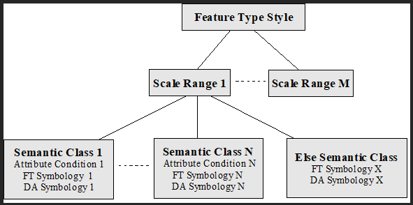
On the first level, all the possible scales are divided into joined but not overlapping ranges. In every scale range, features are classified according to their semantic attributes into a set of classes. Every class is defined by its semantic condition and holds a symbology for the symbolized feature type and symbology (optionally) for its graphic tags. In every scale range, a completely different symbology including completely different classification into semantic classes can be defined. But only one type of semantic classification is allowed in one scale range.
Features are dynamically symbolized in these steps:
- First of all, the scale range is chosen according to actual view scale.
- Only the semantic classes belonging to the chosen scale range are taken into account. The system tries to classify every feature instance to one of the semantic classes. If it succeeds, the feature is symbolized with the specified symbology.
- In case that the feature does not pass through any of the semantic classes conditions, it is symbolized with so called else class symbology.
If else class symbology is not explicitly defined, the features belonging to the else class are symbolized with their static symbology.
Semantic classification
Depending on the types of attribute conditions there are three types of semantic classification allowed.
General classification
General classification allows its classes to define any semantic attributes conditions. The conditions must be written down in the form of logical addition (OR operation) of logical multiplications (AND operation) of single attribute conditions. For example:
(material = 'copper' AND length > 3) OR (material = 'aluminium')
The conditions are written in the form of OGC filters in xml metadata.
Discrete classification
Discrete classification classifies features according to any number of its attributes that must have codelist reference type. Only one equal (= operation) is allowed for every feature attribute in one semantic class. The logical multiplication (AND operation) of single attribute conditions then defines the resulting class condition. In other words, it is possible to assign different symbology to any combination of discrete values of codelist reference type attributes.
Interval classification
Interval classification classifies features according one of their attributes that must have decimal data type. Any class then represents an interval of the attribute possible values.
Combined classification
Combined classification allows to classify features using all of classification methods mentioned above. For each property can be selected different classification method; the final symbology of the feature type is a combination of those individual methods.
Themes
Themes are collections of previously discussed feature type styles. Usually, themes group feature type styles for feature types which are used at the same time. Themes are typically applied to layers (templates, selection sets) so that it’s not necessary to apply individual feature type styles.
One theme cannot include two feature type styles for the same feature type.
Rules
Here, it is necessary to switch from previously defined logical model to physical structure of xml file. To adhere to SE standard as much as possible, the above discussed logical model of feature type style is physically written down in the set of SE rules. Generally, the rule contains both scale and attribute condition and symbolizers of appropriate types. Still the logical model must be reconstructable from the rules.
There are six types of rules:
-
Static Rule (staticRule) – Does not contain neither scale nor attribute condition. Just changes feature type static symbology with another static symbology in a feature type style. Cannot be combined with any other rule within a feature type style.
-
Scale Only Rule (scaleOnlyRule) – Does not contain any attribute condition. Changes symbology according to view scale only. Cannot be combined with any other rule within a scale range.
-
General Rule (rule)– Contains an attribute condition and optionally a scale condition. Used for general semantic classification. Can be combined only with other general rules within a scale range.
-
Discrete Rule (discreteRule)- Contains an attribute condition and optionally a scale condition. Used for discrete semantic classification. Can be combined only with other discrete rules within a scale range.
-
Interval Rule (intervalRule)- Contains an attribute condition and optionally a scale condition. Used for interval semantic classification. Can be combined only with other interval rules within a scale range.
-
Combined Rule (combinedRule) – Used for combined semantic classification. Cannot be combined with any other rule within a scale range. Combined semantic classification is discussed in special chapter 9.2.6.
The rules must be defined in such way that at most one rule for any feature and view scale is defined.
In the following example, dynamic symbology for feature type Main Pipeline Segment is defined. Three scale ranges with following classifications are defined:
- Further than 1:2000
- Main pipeline segments are not displayed in this scale range at all so
scaleOnlyRulewithhiddenScaleset totrueis used and no symbology is defined.
- Main pipeline segments are not displayed in this scale range at all so
- From 1:2000 to 1:1000
- No semantic classification of main pipeline segments is required in this scale range so
scaleOnlyRulewith required symbology is used.
- No semantic classification of main pipeline segments is required in this scale range so
- Closer than 1:1000
- Main pipeline segment features are symbolized according their lengths (
at_5012002) in three classes: shorter than 5 m, from 5 m to 10 m and longer than 10 m. So, interval classification with threeintervalRuleelements is defined.
- Main pipeline segment features are symbolized according their lengths (
Example: Dynamic symbology definition (thematization.xml).
<ber:featureTypeStyleArray>
<ber:featureTypeStyle>
<se:Name>fs_1</se:Name>
<se:Title>Main Pipeline Segment</se:Title>
<se:Abstract>Main Pipeline Segment</se:Abstract>
<se:FeatureTypeName>ft_5012100</se:FeatureTypeName>
<ber:intervalRule defaultScale="true">
<se:Title>Length[m]: 0-5</se:Title>
<ogc:Filter>
<ogc:PropertyIsLessThanOrEqualTo>
<ogc:PropertyName>at_5012002</ogc:PropertyName>
<ogc:Literal>5</ogc:Literal>
</ogc:PropertyIsLessThanOrEqualTo>
</ogc:Filter>
<se:MaxScaleDenominator>1000</se:MaxScaleDenominator>
<ber:lineSymbolizer>
<se:Stroke>
<se:GraphicStroke>
<se:Graphic>
<se:ExternalGraphic>
<se:OnlineResource xlink:href="system.linestyle#solid"/>
<se:Format/>
</se:ExternalGraphic>
</se:Graphic>
</se:GraphicStroke>
<se:SvgParameter name="stroke">#ff0000</se:SvgParameter>
<se:SvgParameter name="stroke-opacity">1.0</se:SvgParameter>
<se:SvgParameter name="stroke-width">1</se:SvgParameter>
</se:Stroke>
</ber:lineSymbolizer>
</ber:intervalRule>
<ber:intervalRule defaultScale="true">
<se:Title>Length[m]: 5-10</se:Title>
<ogc:Filter>
<ogc:PropertyIsBetween>
<ogc:PropertyName>at_5012002</ogc:PropertyName>
<ogc:LowerBoundary>
<ogc:Literal>5</ogc:Literal>
</ogc:LowerBoundary>
<ogc:UpperBoundary>
<ogc:Literal>10</ogc:Literal>
</ogc:UpperBoundary>
</ogc:PropertyIsBetween>
</ogc:Filter>
<se:MaxScaleDenominator>1000</se:MaxScaleDenominator>
<ber:lineSymbolizer>
<se:Stroke>
<se:GraphicStroke>
<se:Graphic>
<se:ExternalGraphic>
<se:OnlineResource xlink:href="resource.xml#ls_2"/>
<se:Format/>
</se:ExternalGraphic>
</se:Graphic>
</se:GraphicStroke>
<se:SvgParameter name="stroke">#00FF00</se:SvgParameter>
<se:SvgParameter name="stroke-opacity">1.0</se:SvgParameter>
<se:SvgParameter name="stroke-width">2</se:SvgParameter>
</se:Stroke>
</ber:lineSymbolizer>
</ber:intervalRule>
<ber:intervalRule defaultScale="true">
<se:Title>Length[m]: 10-></se:Title>
<ogc:Filter>
<ogc:PropertyIsGreaterThan>
<ogc:PropertyName>at_5012002</ogc:PropertyName>
<ogc:Literal>10</ogc:Literal>
</ogc:PropertyIsGreaterThan>
</ogc:Filter>
<se:MaxScaleDenominator>1000</se:MaxScaleDenominator>
<ber:lineSymbolizer>
<se:Stroke>
<se:GraphicStroke>
<se:Graphic>
<se:ExternalGraphic>
<se:OnlineResource xlink:href="resource.xml#ls_3"/>
<se:Format/>
</se:ExternalGraphic>
</se:Graphic>
</se:GraphicStroke>
<se:SvgParameter name="stroke">#0000ff</se:SvgParameter>
<se:SvgParameter name="stroke-opacity">1.0</se:SvgParameter>
<se:SvgParameter name="stroke-width">3</se:SvgParameter>
</se:Stroke>
</ber:lineSymbolizer>
</ber:intervalRule>
<ber:scaleOnlyRule>
<se:MinScaleDenominator>1000</se:MinScaleDenominator>
<se:MaxScaleDenominator>2000</se:MaxScaleDenominator>
<ber:lineSymbolizer>
<se:Stroke>
<se:GraphicStroke>
<se:Graphic>
<se:ExternalGraphic>
<se:OnlineResource xlink:href="system.linestyle#solid"/>
<se:Format/>
</se:ExternalGraphic>
</se:Graphic>
</se:GraphicStroke>
<se:SvgParameter name="stroke">#0000ff</se:SvgParameter>
<se:SvgParameter name="stroke-opacity">1.0</se:SvgParameter>
<se:SvgParameter name="stroke-width">4</se:SvgParameter>
</se:Stroke>
</ber:lineSymbolizer>
</ber:scaleOnlyRule>
<ber:scaleOnlyRule hiddenScale="true">
<se:MinScaleDenominator>2000</se:MinScaleDenominator>
</ber:scaleOnlyRule>
</ber:featureTypeStyle>
...
</ber:featureTypeStyleArray>
<ber:themeArray>
<ber:theme>
<se:Name>th_3</se:Name>
<se:Title>Main Pipeline – interval+scale</se:Title>
<se:Abstract>Main Pipeline - interval+scale</se:Abstract>
<ber:ftStyleRefs>
<ber:ftStyle refId="fs_1"/>
<ber:ftStyle refId="fs_2"/>
<ber:ftStyle refId="fs_3"/>
</ber:ftStyleRefs>
</ber:theme>
...
</ber:themeArray>
Graphic tags dynamic symbology
Graphic tags can be dynamically symbolized together with their feature types.
Example: Displayable attributes dynamic symbology definition.
      <ber:intervalRule id="rule_456_1" name="Length[m]: 0-5">
        <ogc:Filter>
          <ogc:PropertyIsBetween>
            <ogc:PropertyName>at_5012002</ogc:PropertyName>
            <ogc:LowerBoundary>
              <ogc:Literal>0</ogc:Literal>
            </ogc:LowerBoundary>
            <ogc:UpperBoundary>
              <ogc:Literal>5</ogc:Literal>
            </ogc:UpperBoundary>
          </ogc:PropertyIsBetween>
        </ogc:Filter>
        <ber:lineSymbolizer>
          <se:Stroke>
            <se:GraphicStroke>
              <se:Graphic>
                <se:ExternalGraphic>
                  <se:OnlineResource xlink:href="system.linestyle#solid"/>
                  <se:Format/>
                </se:ExternalGraphic>
              </se:Graphic>
            </se:GraphicStroke>
            <se:SvgParameter name="stroke">#ff0000</se:SvgParameter>
            <se:SvgParameter name="stroke-opacity">1.0</se:SvgParameter>
            <se:SvgParameter name="stroke-width">1</se:SvgParameter>
          </se:Stroke>
        </ber:lineSymbolizer>
        <ber:textSymbolizer>
          <se:Geometry>
            <ogc:PropertyName>ft_5012100_gtda_5012101/gtda_5012101_1
            </ogc:PropertyName>
          </se:Geometry>
          <se:Fill>
            <se:SvgParameter name="fill">#FF0000</se:SvgParameter>
          </se:Fill>
          <ber:fontHeight>2</ber:fontHeight>
        </ber:textSymbolizer>
      </ber:intervalRule>
In this example, an interval rule for feature type Main Pipeline Segment is defined. Within this rule, segments shorter than 5 m are symbolized together with their graphic tags (displayable attributes) – install dates (ft_5012100_gtda_5012101). In contrast to feature type dynamic symbology definition, it is necessary to identify the graphic tag type and the component type. For this reason, PropertyName inside Geometry element is present in graphic tag dynamic symbolizer.
Combined semantic classification
Combined semantic classification enables independent resymbolization of particular symbology properties (i.e. color, opacity, weight, ...) In other words, various semantic classifications (for various symbology properties) can be combined into one feature type symbolizer. It is possible to modify each symbology properties according to different semantic attributes and different classification types.
For any symbology property, one of these definitions can be used:
-
no change – property is omitted, original static symbology value is used
-
new static symbology - new static value replaces original static symbology value
-
direct symbology - the value is taken directly from the given feature attribute
-
interval classification
-
discrete classification
-
general classification
If a discrete classification is used in a combined classification, just one attribute can be used. It is a limitation comparing to the standard discrete classification.
So far it is not possible to use the combined classification for collections and graphic tags.
In the following example, a feature type style with the combined classification is defined:
- in a scale smaller than 1:1000, the feature type is not displayed at all
- in a scale larger than 1:1000, the combined classification is used
- line style is changed according to attribute
at_5010007- general classification is used
- features with the value beginning with 6 are drawn using line style
ls_1, the others (elseClass) use stylels_2
- line color is changed according to attribute
at_ 5012003- discrete classification is used
- color is defined for values 2, 3, 4, 5, 10; for all other values (
elseClass), one color is defined
- line width is changed according to
at_ 5012102- interval classification is used
- three classes are defined
- < 6200 bar
- >= 6200 bar to < 6400 bar
- >= 6400 bar
- other symbolizer attributes are not changed – they are defined by a static feature type symbolizer
Example: Combined semantic classification definition.
<ber:featureTypeStyle id="fs_321"
name="Main Pipeline Segment - combined">
<ber:description>Main Pipeline Segment - hide + combined</ber:description>
<se:FeatureTypeName>ft_5012100</se:FeatureTypeName>
<ber:combinedRule id="rule_80000"
name="Material->color; Pressure->line-width"
defaultScale="true">
<se:MaxScaleDenominator>1000</se:MaxScaleDenominator>
<ber:lineSymbolizer>
<se:Stroke>
<se:GraphicStroke>
<se:Graphic>
<se:ExternalGraphic>
<ber:OnlineResource>
<ber:generalClassification>
<!-- line style changed by combined classification -->
<ber:generalClass>
<ogc:Filter>
<ogc:PropertyIsLike wildCard="%" singleChar="_"
escape="\">
<ogc:PropertyName>at_5010007</ogc:PropertyName>
<ogc:Literal>6%</ogc:Literal>
</ogc:PropertyIsLike>
</ogc:Filter>
<ber:value id="fsv_01">resource.xml#ls_1</ber:value>
</ber:generalClass>
<ber:elseClass>
<ber:value id="fsv_02">resource.xml#ls_2</ber:value>
</ber:elseClass>
</ber:generalClassification>
</ber:OnlineResource>
<se:Format/>
</se:ExternalGraphic>
</se:Graphic>
</se:GraphicStroke>
<se:SvgParameter name="stroke">
<ber:recode fallbackValue="#888888">
<!-- color changed by discrete classification -->
<se:LookupValue>
<ogc:PropertyName>at_5012003/ca_10201</ogc:PropertyName>
</se:LookupValue>
<ber:mapItem>
<ber:data>2</ber:data>
<ber:value id="fsv_11">#FF0000</ber:value>
</ber:mapItem>
<ber:mapItem>
<ber:data>4</ber:data>
<ber:value id="fsv_12">#FF0000</ber:value>
</ber:mapItem>
<ber:mapItem>
<ber:data>5</ber:data>
<ber:value id="fsv_13">#FF0000</ber:value>
</ber:mapItem>
<ber:mapItem>
<ber:data>3</ber:data>
<ber:value id="fsv_14">#00FF00</ber:value>
</ber:mapItem>
<ber:mapItem>
<ber:data>10</ber:data>
<ber:value id="fsv_15">#0000FF</ber:value>
</ber:mapItem>
<ber:elseClass>
<ber:value id="fsv_16">#888888</ber:value>
</ber:elseClass>
</ber:recode>
</se:SvgParameter>
<se:SvgParameter name="stroke-width">
<se:Categorize fallbackValue="1">
<se:LookupValue>
<ogc:PropertyName>at_5012102</ogc:PropertyName>
</se:LookupValue>
<ber:value id="rule_80020">1</ber:value>
<se:Threshold>6200</se:Threshold>
<ber:value id="rule_80021">2</ber:value>
<se:Threshold>6400</se:Threshold>
<ber:value id="rule_80022">3</ber:value>
</se:Categorize>
</se:SvgParameter>
</se:Stroke>
</ber:lineSymbolizer>
</ber:combinedRule>
<ber:scaleOnlyRule id="rule_80100" hiddenScale="true">
<se:MinScaleDenominator>1000</se:MinScaleDenominator>
</ber:scaleOnlyRule>
</ber:featureTypeStyle>
-
The metadata notation is based on OGC standard Symbology Encoding (SE) 1.1.0.
-
elseClass - Defined for each partial general and discrete classification. It makes no sense to define elseClass for an interval classification. The whole possible range of attribute values is always covered by a definition.
-
tresholdsBelongTo - Defines whether the split points belong to a preceding or succeeding (default) interval.
-
fallbackValue - In SE specification defined as “a value of a symbolizer attribute which should be used when the system is not able to evaluate the defined classification”. LIDS does not use this value. It is preserved because of the compatibility with SE XSD schemes. It cannot be used for our
elseClassrule definition as it cannot have ID.
Symbology tokens
Symbology tokens are values of already evaluated classifications for feature type styles. Symbology tokens for individual features are stored in the database, in the feature table. The values of the symbology tokens are evaluated automatically by LIDS Application server when creating / updating the features.
The tokens are needed by LIDS Application Server when rendering the features using dynamic symbology. Only such dynamic symbology which is supported by generated symbology tokens can be used by Application Server.
The tokens are generated for:
- styles referred as
dynamicSymbologyin feature type definition in model.xml - themes which include attribute
utilizedForWMS=”true”in thematization.xml
This means, every feature can have symbology tokens from more styles stored in the feature table.
Symbology tokens can be used to optimize dynamic symbology performance also in LIDS Edit / Explorer clients. LIDS Edit / Explorer clients can evaluate dynamic symbology rules by themselves. But in such cases, it’s necessary for the client to download not only the geometry but also all semantic attributes in order to be able to evaluate the dynamic symbology classification. This is time consuming. If the symbology tokens exist for particular dynamic symbology definition, client application can apply the symbology using the symbology tokens directly and it’s not necessary to download also the attributes. This improves the performance of downloading the graphics significantly.
Following modes of downloading graphics into LIDS Edit / Explorer can occur:
-
static symbology – no need to evaluate classification, just the geometry is downloaded to the clients
-
dynamic symbology based on symbology tokens – classification is already evaluated, symbology tokens are downloaded together with the geometry, no semantics is downloaded to the clients
-
dynamic symbology without symbology tokens – classification has to be evaluated by the client application, semantics has to be downloaded to the clients additionally to the geometry